Hierarchical Schematic Entry
Schematics can be organised into multiple levels in a hierarchy. Typically the top level would contain a number of blocks, each of which represents an underlying child schematic. Each of the child schematics can in turn contain more blocks.
You can create a hierarchical schematic in one of two ways:
The schematic and its symbol are stored within the same file. The combined element is known as a component and is usually given the file extension .SXCMP.
All the methods for creating hierarchical schematics described in this section use components.
In this topic:
Top-Down Method
Creating Part Symbol
Select schematic menu . This will open the graphical symbol editor. See Graphical Symbol Editor for details. Note that the symbol you create must be given a Ref property typically with the initial value U? and a Model property which must have the value X.
Placing Symbol
If the schematic containing the block has never been saved ('untitled' in caption bar) you must save it now. This is so that the schematic has a title. This step is only necessary if the schematic has never been saved before.
Component module ports in underlying schematic do not match symbol pinsdisplayed in the command shell. This warning may be ignored at this point.
Creating Schematic for Block
- Select the symbol whose schematic you wish to define then select schematic menu . Note the symbol must have been saved as a component as described above.
- A new schematic sheet will be opened with a number of module port symbols already placed. These will be named according to the pin names of the block. You must use these to make connections to the outside world.
Bottom-up method
Creating Schematic
- Open or draw schematic. It must have at least one Module Port symbol on it. To place a module port, use schematic menu .
- Save the schematic as a component. Select menu Save As... then select Components from Save as type: list.
Creating Symbol for Schematic
- Select
- A graphical symbol editor window will be opened with a default symbol generated from the number, orientation and names of the module ports on the schematic.
- The symbol created can be saved straight away or you can edit it to suit your requirements. To save it, in the symbol editor window, select the menu . You will not usually need to change any of the settings in the dialog. Just press Ok to close.
Placing - Full vs Relative Path
Components can be placed using their full path or a relative path.
When placed with a full path, the component file is referenced using its full file system path name (e.g. C:\Projects\Proj123\amplifier.sxcmp. This allows the schematic file that uses the component to be freely moved as long as the component file stays in the same place. However if the component file is moved the schematic will no longer be able to locate it.
When placed with a relative path, the component file is referenced with a file system path name relative to the schematic that uses it. Most likely the component file will be in the same directory (or folder) as the schematic and will therefore be referenced by its file name alone. (E.g. amplifier.sxcmp). This allows the schematic file and component file to be moved together to any location but they may not be moved individually.
In general we recommend using relative paths wherever possible. The exception is when placing a component that is held in a general library, for example a standard cell used in an integrated circuit design.
To place a component using its full path
Select schematic menu . Select a component file then place in the normal way.
To place a component using its relative path
Select schematic menu . Select a component file then place in the normal way.
Using symbolic constants
SIMetrix has a facility to define path names using symbolic constants. This system allows absolute locations for files to be defined using a single value and thus making it easy to change that location. See Symbolic Path Names for further details.
Windows/Linux Inter-operability
Paths are stored on each schematic instance using the UNIX directory separator, that is the forward slash '/'. This is provided for compatibility with older versions that run under Linux. (SIMetrix for Linux is no longer available.) This allows schematics created using a Windows version to be used with a legacy Linux version. In most cases Windows accepts a forward slash as a directory separator whereas Linux does not accept a back slash.
Connecting Buses in a Hierarchy
Overview
Bus connections can be passed through a hierarchy in much the same way as normal single wire connections. Bus connections are defined by the underlying schematic. The symbol representing the schematic does not require any special treatment.
Creating Bus Connections Using the Bottom Up Method
- Enter the schematic in the usual way.
- To define a bus connection, place the part Hierarchy | Place Module Bus Port instead of the usual Module Port. Select the device and press F7 to define the port name and bus size (i.e. the number of wires in the bus).
- Save schematic as a 'Component'
- Select menu
- Edit symbol if required then save
Changing the Bus Offset in the Parent Schematic
- Select the label next to the bus pin. This will be of the form [A..B] where A is the start wire (default is 0) and B is the final wire. Note that if you edited an existing symbol to add a bus connection, you may not see this label. If so select the component then menu .
- Press F7 then enter the new offset and OK. You will see the label change accordingly. For example, suppose the bus has 8 wires as defined in the child schematic. To begin with the label will be [0..7] and will therefore connect to bus wire 0 to 7. If you change the offset to, for example, 4, the label will change to [4..11] meaning that the connection will now be made to wires 4 to 11.
Changing a Non-bus Connection to a Bus Connection
- In the child schematic change the Module Port to a Module Bus Port and edit as appropriate.
- In the parent schematic, select the block then menu . This will update the schematic to show the bus connection on the hierarchical block.
Changing the Size of a Bus Connection
- In the child schematic, select the appropriate Module Bus Port.
- Press F7 and enter the new size as required.
- In the parent schematic, select the block then menu .
Global Nets
You can access any net at the top level of a hierarchy using a terminal symbol and prefixing the name with '#'.
For example, suppose you have a net at the top level called VCC. You can access this net at any level of the hierarchy without having to pass the connection by connecting a terminal symbol () and then assigning it the name #VCC.
Global Pins
Supposing you have two instances of a hierarchical block which you wish to connect to different supply rails. To do this you would need to connect the supplies - say VCC - to pins at the top level with explicit (i.e. non-global) connections at the lower levels. So every child schematic at lower levels would also need VCC pins.
However, it is sometime convenient to hide these connections. When there is only one supply for an entire design, this can be done using global nets. However, in the scenario we described above, there are two versions of VCC so we would not be able to use a global net in this case.
A solution to this is to use a feature of SIMetrix called Global Pins. Global pins are defined during symbol definition. Once a pin is defined as global, a net of the same name will be available in all child schematics at all levels without the need for it to be explicitly passed.
Example
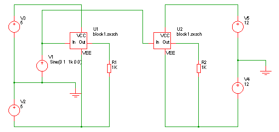 |
Top Level Schematic |
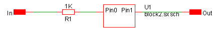 |
Block 1 |
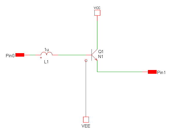 |
Block 2 |
In the above example, VCC and VEE connections have been made in block2 without them having to be passed via the parent block1.
The above trivial example is supplied as an example. See Examples/Hierarchy/Global Pins.
Creating Global Pins
To define a global pin. select the symbol editor menu . Double click on the pin you wish to assign as global and select Yes.
Passing Parameters Through a Hierarchy
To pass parameters through a hierarchy, assign a PARAMS property then give it a value to assign each parameter you wish to pass (e.g. PARAM1=10 PARAM2=57). See supplied example in folder Examples/Hierarchy/Passing Parameters.
This feature works in both SIMetrix and SIMPLIS runs.
Adding Parameters to a Symbol
The PARAMS property is most easily added in the symbol editor when the symbol for the hierarchical block is created. This is the procedure:
- Open the symbol in the symbol editor. If you are editing a hierarchical symbol that has already been created and placed on a schematic, select the symbol then menu .
- In the symbol editor, select menu Property/Pin Add Property. This will open the Add Property dialog box.
- In the Name box enter PARAMS.
- In the Value box enter the parameter names and their default values. For example: PARAM1=10 PARAM2=57
- You can leave the remaining settings at their default values or edit as desired.
- Click Ok.
- Select menu , then click Ok to close. Close symbol editor window if desired.
If you have already placed instances of the symbol you can update it so that it acquires the new PARAMS property you have just added to the symbol definition. To do this proceed as follows:
- Select the instance of the symbol in the schematic editor.
- Select right click menu Update Properties... . Accept the default action - this will add any properties missing from the existing instance but present in the symbol definition.
Editing Parameters
- Select hierarchical instance.
- Select right click menu Edit/Add Properties....
- Double click the item with name PARAMS
- Enter new values as required in the Value box.
Accessing Parameters in the Child Schematic
You can use any parameter defined on the symbol in an expression to define a component value or model value. You should enclose the expression with curly braces: '{' and '}'.
Missing Hierarchical Blocks
When a hierarchical schematic is opened, SIMetrix needs to locate the component files that contain the symbols used for each hierarchical block. If, however, the file for a particular component is missing or is in the wrong location, then SIMetrix will not be able to display that component's symbol. Unlike library symbols, component symbols are not stored locally in the schematic file.
In order to make it possible to resolve the problem, SIMetrix instead puts a place holder symbol in place of the missing symbol. The place holder symbol is a diagonal cross.
Repairing Missing Components
If a component is missing you can either edit the schematic to identify the new location of the component, or you can move files around so that the components are once again in the expected locations.
To edit the schematic, select the place holder symbol then menu .
To relocate files, use the system's file handling tools to move the component files, then select menu .
Highlighting
The schematic highlighting features will work through a hierarchy. The menus and will highlight a selected net within the displayed schematic and any connected nets in other schematics in the same hierarchy. But note the following:
- In very large hierarchies, it is possible that the mechanism that traces through the hierarchy to identify connected nets can noticeably slow down the time taken to descend into a new schematic. Hierarchical highlighting can be disabled if this becomes a problem. See menu then check Disabled under Hierarchy Highlighting
- Connectivity information in SIMetrix schematics is normally only generated when a netlist is created. For this reason it is possible for highlighting to be incomplete if a schematic has been edited since a simulation was last run. The highlighting algorithms seeks to minimise this problem by running the netlister at certain times, but for performance reasons does not netlist the whole hierarchy. You can use the menu to resolve this problem. This will netlist the complete hierarchy and rebuild the highlights from scratch.
Copying a Hierarchy
A complete hierarchy may be copied for archival purposes subject to certain conditions as follows:
- The hierarchy must use relative paths throughout
- All child components must be either in the same directory as the root or in a directory that is a direct descendant of the root.
| ◄ Fundamentals | Schematic Annotations ▶ |