Using the Simulator with the Schematic Editor
Full documentation on using the SIMetrix schematic editor for simulation is described in the SIMetrix User's manual. However, just a few features of the schematic editor are of particular importance for running the simulator and for convenience their description is repeated here.
In this topic:
Adding Extra Netlist Lines
The analysis mode selected using the schematic editor's menu is stored in text form in the schematic's simulator command window. If you wish, it is possible to edit this directly. Sometimes this is quicker and easier than using the GUI especially for users who are familiar with the command syntax.
Note that the text entered in the simulator command window and the Choose Analysis dialog settings remain synchronised so you can freely switch between the two methods.
To open the simulator command window, select the schematic then press the F11 key. It has a toggle action, pressing it again will hide it. If you have already selected an analysis mode using the Choose Analysis dialog, you will see the simulator statements already present.
The window has a popup menu selected with the right key. The top item Edit file at cursor will open a text editor with the file name pointed to by the cursor or selected text item if there is one.
The simulator command window can be resized using the splitter bar between it and the schematic drawing area.
You can add anything you like to this window not just simulator commands. The contents are simply appended to the netlist before being presented to the simulator. So, you can place .PARAM statements, device models, inductor coupling specifications, .OPTIONS statements or simply comments. The Choose Analysis dialog will parse and possibly modify analysis statements and some .OPTIONS settings but will leave everything else intact.
Adding Simulator Commands to a Schematic
As well as the F11 window you can also add simulator commands to the schematic itself so that they can be easily viewed alongside the circuit being simulated.
This is done using the Control Block symbol. This is available from menu
Displaying Net and Pin Names
It is sometimes necessary to know the name used for a particular net on the schematic to be referenced in a simulator statement (such as .NOISE) or for an arbitrary source input. There are two approaches:
- Find out the default name generated by the schematic editor's netlist generator. To do this, move the mouse cursor over the net of interest then observe the netname in the status bar in the form "NET=???".
- Force a net name of your choice. For this, use a terminal or small terminal symbol. These can be found under the menu. After placing on the schematic, select it then press F7 to edit its name. This name will be used to name the net to which it is connected.
Editing Device Parameters
To use any of the additional parameters in a schematic, use the Parameters button in the dialog box opened by F7 or the equivalent menu. For example you see this box when editing a resistor:
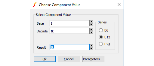
Pressing the Parameters button will open another dialog from which you can edit parameter values:
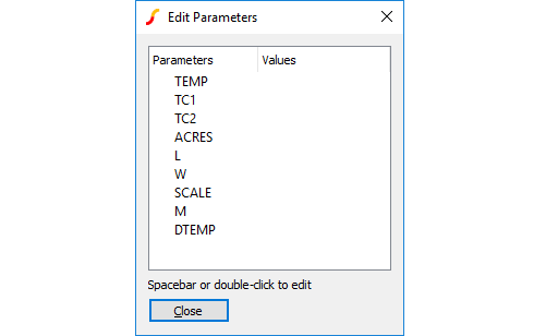
You can also bring up this box directly using the right click menu Edit Additional Parameters....
Editing Literal Values - Using shift-F7
The above method is not infallible as it requires the schematic editor to know about the device being edited. In some circumstances, this will require special properties to be present on the symbol and these may have not been defined (for example something to tell the schematic what level a MOSFET is).
Another situation where the usual device editing methods may be unsuitable is when you need to define a parameter as an expression.
In these situations you can use shift-F7. This will edit the device's literal value including any model names exactly as it will be placed in the netlist. shift-F7 bypasses all smart algorithms and presents you with the raw values and you must also supply raw values. For example, here is what you might enter for a MOSFET referencing a model called N1
N1 L={LL-2*EDGE} W={WW-2*EDGE}
Note the model name must be included.
| ◄ What is in This Manual | Running in non-GUI Mode ▶ |