Diode - Level 1 and Level 3
In this topic:
Netlist Entry
Dxxxx n+ n- model_name [area] [OFF] [IC=vd] [TEMP=local_temp]
+ [PJ=periphery] [L=length] [W=width] [M=mult] [DTEMP=dtemp]
| n+ | Anode |
| n- | Cathode |
| model_name | Name of model defined in a .MODEL statement. Must begin with a letter but can contain any character except whitespace and '.'. |
| area | Area multiplying factor. Area scales up the device. E.g. an area of 3 would make the device behave like 3 diodes in parallel. Default is 1. |
| OFF | Instructs simulator to calculate operating point analysis with device initially off. This is used in latching circuits such as thyristors and bistables to induce a particular state. See .OP for more details. |
| vd | Initial condition for diode voltage. This only has an effect if the UIC parameter is specified on the .TRAN statement. |
| local_temp | Local temperature. Overrides specification in .OPTIONS or .TEMP statements. |
| periphery | Level 3 only. Junction periphery used for calculating sidewall effects. |
| length | Level 3 only. Used to calculate area. See below. |
| width | Level 3 only. Used to calculate area. See below. |
| mult | Device multiplier. Equivalent to putting mult devices in parallel. |
| dtemp | Differential temperature. Similar to local_temp but is specified relative to circuit temperature. If both TEMP and DTEMP are specified, TEMP takes precedence. |
Examples
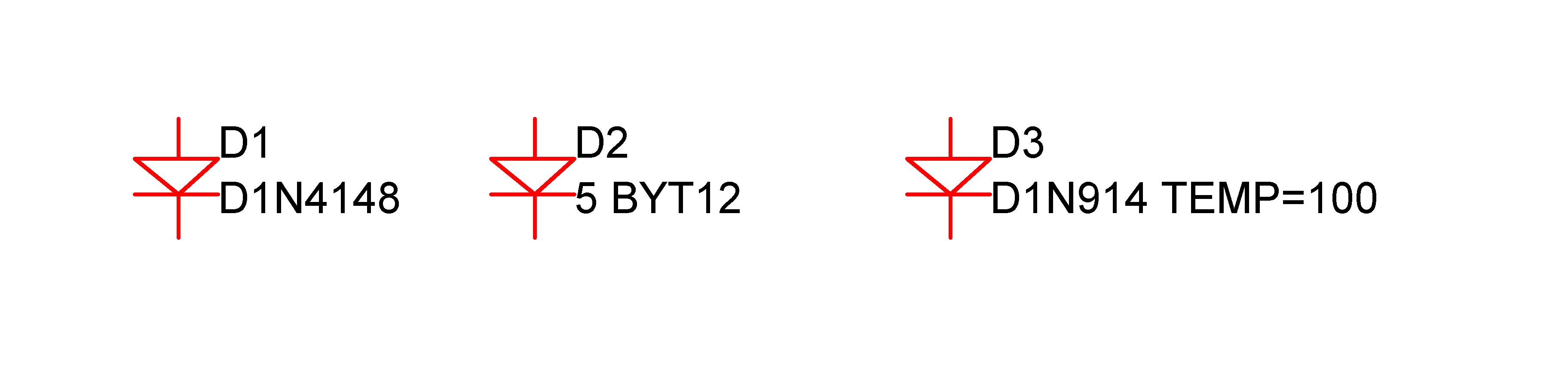
Diode Model Syntax
.model modelname D ( LEVEL=[1|3] parameters )
Diode Model Parameters - Level = 1
The symbols '???MATH???\times???MATH???' and '???MATH???\div???MATH???' in the Area column means that the specified parameter should be multiplied or divided by the area factor respectively.
| Name | Description | Units | Default | Area |
| IS | Transport saturation current | A | 1e-14 | ???MATH???\times???MATH??? |
| ISR | Recombination current parameter | A | 0 | ???MATH???\times???MATH??? |
| N | Emission coefficient | 1 | ||
| NR | Emission Coefficient for ISR | 2 | ||
| IKF | High injection knee current | A | ???MATH???\infty???MATH??? | ???MATH???\times???MATH??? |
| RS | Series resistance | ???MATH???\Omega???MATH??? | 0 | ???MATH???\div???MATH??? |
| TT | Transit time | sec | 0 | |
| CJO or CJ0 | Zero bias junction capacitance | F | 0 | ???MATH???\times???MATH??? |
| VJ | Junction potential | V | 1 | |
| M | Grading coefficient | 0.5 | ||
| EG | Energy gap | eV | 1.11 | |
| XTI | Saturation current temperature exponent | 3 | ||
| KF | Flicker noise coefficient | 0 | ||
| AF | Flicker noise exponent | 1 | ||
| FC | Forward bias depletion capacitance coefficient | 0.5 | ||
| BV | Reverse breakdown voltage | V | ???MATH???\infty???MATH??? | |
| IBV | Current at breakdown voltage | A | 1e-10 | ???MATH???\times???MATH??? |
| TNOM, T_MEASURED | Parameter measurement temperature | ???MATH???°???MATH???C | 27 | |
| T_ABS | If specified, defines the absolute model temperature overriding the global temperature defined using .TEMP | ???MATH???°???MATH???C | - | |
| T_REL_ GLOBAL | Offsets global temperature defined using .TEMP. Overridden by T_ABS | ???MATH???°???MATH???C | 0 | |
| TRS1 | First order tempco RS | /???MATH???°???MATH???C | 0 | |
| TRS2 | Second order tempco RS | /???MATH???°???MATH???C???MATH???^2???MATH??? | 0 | |
| TBV1 | First order tempco BV | /???MATH???°???MATH???C | 0.0 | |
| TBV2 | Second order tempco BV | /???MATH???°???MATH???C???MATH???^2???MATH??? | 0.0 | |
| NBV | Reverse breakdown ideality factor | 1.0 | ||
| NBVL | Low-level reverse breakdown ideality factor | 1.0 | ||
| IBVL | Low-level reverse breakdown knee current | Amp | 0.0 | ???MATH???\times???MATH??? |
| TIKF | IKF temperature coefficient | 0.0 |
| Notes | The dc characteristics of the diode are determined by the parameters IS, N, ISR, NR and IKF. An ohmic resistance, RS, is included. Charge storage effects are modelled by a transit time, TT, and a non-linear depletion layer capacitance which is determined by the parameters CJO, VJ, and M. The temperature dependence of the saturation current is defined by the parameters EG, the energy and XTI, the saturation current temperature exponent. Reverse breakdown is modelled by an exponential increase in the reverse diode current and is determined by the parameters BV and IBV (both of which are positive numbers). |
Diode Model Parameters - Level = 3
| Name | Description | Units | Default |
| AF | Flicker noise exponent | 1.0 | |
| BV, VB, VAR, VRB | Reverse breakdown voltage | V | ???MATH???\infty???MATH??? |
| CJO, CJ | Zero bias junction capacitance | F | 0.0 |
| CJSW, CJP | Zero bias sidewall capacitance | F | 0.0 |
| CTA | CJO temp coefficient. (TLEVC=1) | ???MATH???°???MATH???C???MATH???^{-1}???MATH??? | |
| CTP | CJSW temp coefficient. (TLEVC=1) | ???MATH???°???MATH???C???MATH???^{-1}???MATH??? | |
| EG | Energy gap | ev | 1.11 (see below) |
| FC | Forward bias depletion capacitance coefficient | 0.5 | |
| FCS | Forward bias sidewall capacitance coefficient | 0.5 | |
| GAP1 | 7.02e-4 - silicon (old value) 4.73e-4 - silicon 4.56e-4 - germanium 5.41e-4 - gallium arsenide | eV/???MATH???°???MATH??? | 7.02e-4 |
| GAP2 | 1108 - silicon (old value) 636 - silicon 210 - germanium 204 - gallium arsenide | ???MATH???°???MATH??? | 1108 |
| IBV | Current at breakdown voltage | A | 1E-3 |
| IKF, IK | High injection knee current | A | ???MATH???\infty???MATH??? |
| IKR | Reverse high injection knee current | A | ???MATH???\infty???MATH??? |
| IS, JS | Saturation current | A | 1E-14 |
| ISR | Recombination current | A | 0 |
| JSW | Sidewall saturation current | A | 0 |
| KF | Flicker noise exponent | 0 | |
| MJ, M | Grading coefficient | 0.5 | |
| MJSW | Sidewall grading coefficient | 0.33 | |
| N, NF | Forward emission coefficient | 1.0 | |
| NR | Recombination emission coefficient | 2.0 | |
| PHP | Sidewall built in potential | PB | |
| RS | Series resistance | ???MATH???\Omega???MATH??? | 0 |
| SHRINK | Shrink factor | 1.0 | |
| TCV | BV temp coefficient | ???MATH???°???MATH???C-1 | 0 |
| TLEV | Temperature model selector. Valid values: 0, 1, 2 | 0 | |
| TLEVC | Temperature model selector. Valid values: 0 or 1 | 0 | |
| TNOM, TREF | Parameter measurement temperature | 27 | |
| TPB | VJ temp coefficient (TLEVC=1) | V/???MATH???°???MATH???C | 0.0 |
| TPHP | PHP temp. coefficient (TLEVC=1) | V/???MATH???°???MATH???C | 0.0 |
| TRS | RS temp. coefficient | ???MATH???°???MATH???C???MATH???^{-1}???MATH??? | 0.0 |
| TT | Transit time | S | 0.0 |
| VJ, PB | Built-in potential | V | 0.8 |
| XW | Shrink factor | 0.0 | |
| DCAP | Capacitance model (1 or 2) | 1 | |
| SPECTRE_TEMP | (0 or 1) If set to 1, implements energy gap equations and defaults in accordance with Cadence Spectre® with "compatibility=spectre" set | 0 |
If L and W instance parameters are supplied, the diode is scaled by the factor: M*(L*SHRINK-XW)*(W*SHRINK-XW) otherwise it is scaled by M*AREA.
EG parameter default is 1.124481 if SPECTRE_TEMP=1 or 1.16 if TLEV=2 and SPECTRE_TEMP=0
Using Hspice Diodes
In Hspice Level 1 diodes are the same as the SIMetrix Level 3 diode. To map Level 3 to Level 1, add this line to the netlist
.OPTIONS HSPICEMODELS=1
.OPTIONS HSPICECOMPATIBILITY=1
See .OPTIONS for more details
M and AREA are instance parameters which default to 1.0
| ◄ Current Source | Diode - Soft Recovery ▶ |