And Gate
Netlist entry:
Axxxx [ in_0 in_1 .. in_n ] out model_name
Connection details
|
Name
|
Description
|
Flow
|
Type
|
Vector bounds
|
|
in
|
Input |
in |
d, vector |
???MATH???2 - \infty???MATH??? |
|
out
|
Output |
out |
d |
n/a |
.MODEL model_name d_and parameters
Model parameters
Device operation
-
If the model parameter OPEN_C is false, The output will be at logic '0' if either input is at logic '0'. Otherwise, if any input is UNKNOWN, the output will be UNKNOWN. Otherwise the output will be at logic '1'.
-
If the model parameter OPEN_C is true the device will be open collector. In this case the output logic state is always '0'. The state of the inputs instead determines the strength of the output. If either input is at logic '0' the output strength will be STRONG. Otherwise if any input is UNKNOWN the output strength will be UNDETERMINED. Otherwise the output strength will be HI-IMPEDANCE allowing a pull-up resistor to force it to the logic '1' state.
Buffer
Netlist entry
Connection details
|
Name
|
Description
|
Flow
|
Type
|
|
in
|
Input |
in |
d |
|
out
|
Output |
out |
d |
.MODEL model_name d_buffer parameters
Model parameters
|
Name
|
Description
|
Type
|
Default
|
Limits
|
|
rise_delay
|
Rise delay |
real |
1nS |
1e-12 ???MATH???- \infty???MATH??? |
|
fall_delay
|
Fall delay |
real |
1nS |
1e-12 ???MATH???- \infty???MATH??? |
|
stored_delay
|
Stored delay (overrides rise_delay and fall_delay) |
real |
0 |
???MATH???0 - \infty???MATH??? |
|
input_load
|
Input load value (F) |
real |
1pF |
none |
|
family
|
See Family parameters
|
string |
UNIV |
none |
|
in_family
|
See Family parameters
|
string |
UNIV |
none |
|
out_family
|
See Family parameters
|
string |
UNIV |
none |
|
out_res
|
See Output Parameters
|
real |
100 |
???MATH???0 - \infty???MATH??? |
|
out_res_pos
|
See Output Parameters
|
real |
out_res |
???MATH???0 - \infty???MATH??? |
|
out_res_neg
|
See Output Parameters
|
|
out_res |
???MATH???0 - \infty???MATH??? |
|
open_c
|
Open collector output |
boolean |
FALSE |
none |
|
min_sink
|
See Output Parameters
|
real |
-0.001 |
none |
|
max_source
|
See Output Parameters
|
real |
0.001 |
none |
|
sink_current
|
See Input Parameters
|
real |
0 |
none |
|
source_current
|
See Input Parameters
|
real |
0 |
none |
|
open_e
|
Open emitter output |
boolean |
FALSE |
none |
|
vsupply
|
See vsupply Parameter
|
real |
5 |
none |
Device Operation
This device is a simple buffer with a single input and output. It can optionally be specified to have an open collector (open_c parameter) or open emitter (open_e parameter) output. Further, if the stored_delay parameter is specified, the device will act as a pure delay. This means that it will pass pulses that are shorter than the delay time whereas normally (delay specified by rise_delay and fall_delay) such pulse would be swallowed (stored_delay is also known as transport delay).
The following table describes the device operation in detail
|
OPEN_C
parameter
|
OPEN_E parameter
|
Input
|
Output state
|
Output strength
|
|
FALSE
|
FALSE |
0 |
0 |
STRONG |
|
FALSE
|
FALSE |
1 |
1 |
STRONG |
|
FALSE
|
FALSE |
UNKNOWN |
UNKNOWN |
STRONG |
|
FALSE
|
TRUE |
0 |
0 |
HI-IMPEDANCE |
|
FALSE
|
TRUE |
1 |
1 |
STRONG |
|
FALSE
|
TRUE |
UNKNOWN |
UNKNOWN |
UNDETERMINED |
|
TRUE
|
FALSE |
0 |
0 |
STRONG |
|
TRUE
|
FALSE |
1 |
0 |
HI-IMPEDANCE |
|
TRUE
|
FALSE |
UNKNOWN |
0 |
UNDETERMINED |
|
TRUE
|
TRUE |
0 |
1 |
HI-IMPEDANCE |
|
TRUE
|
TRUE |
1 |
0 |
HI-IMPEDANCE |
|
TRUE
|
TRUE |
UNKNOWN |
UNKNOWN |
UNDETERMINED |
Note the difference between open emitter and open collector operation. These modes have been designed to be as close to as possible to real devices, in particular their behaviour into an open circuit. An open emitter output, when switching from high to low is likely to follow the voltage on the device's base due to the base-emitter capacitance so the output state follows the input state. An open collector (or open drain) output on the other hand will remain in the low state when its input switches.
Exclusive NOR Gate
Netlist entry
Axxxx [ in_0 in_1 .. in_n ] out model_name
Connection details
|
Name
|
Description
|
Flow
|
Type
|
Vector bounds
|
|
in
|
Input |
in |
d, vector |
???MATH???2 - \infty???MATH??? |
|
out
|
Output |
out |
d |
n/a |
.MODEL model_name d_xnor parameters
Model parameters
Device Operation
-
If the OPEN_C parameter is FALSE, the output is at logic '1' if an even number of inputs are at logic '1'. If any input is UNKNOWN the output will be UNKNOWN, otherwise the output will be at logic '0'.
-
If the model parameter OPEN_C is true the device will be open collector. In this case the output logic state is always '0'. The state of the inputs instead determines the strength of the output. If n even number of inputs are at logic '1' the output strength will be HI-IMPEDANCE allowing a pull-up resistor to force it to the logic '1' state. If any input is UNKNOWN the output strength will be UNDETERMINED. Otherwise the output strength will be STRONG.
Exclusive OR Gate
Netlist entry
Axxxx [ in_0 in_1 .. in_n ] out model_name
Connection details
|
Name
|
Description
|
Flow
|
Type
|
Vector bounds
|
|
in
|
Input |
in |
d, vector |
???MATH???2 - \infty???MATH??? |
|
out
|
Output |
out |
d |
n/a |
.MODEL model_name d_xor parameters
Model parameters
Device Operation
-
If the OPEN_C parameter is FALSE, the output is at logic '1' if an odd number of inputs are at logic '1'. If any input is UNKNOWN the output will be UNKNOWN, otherwise the output will be at logic '0'.
-
If the model parameter OPEN_C is true the device will be open collector. In this case the output logic state is always '0'. The state of the inputs instead determines the strength of the output. If an odd number of inputs are at logic '1' the output strength will be HI-IMPEDANCE allowing a pull-up resistor to force it to the logic '1' state. If any input is UNKNOWN the output strength will be UNDETERMINED. Otherwise the output strength will be STRONG.
Inverter

Netlist entry
Connection details
|
Name
|
Description
|
Flow
|
Type
|
|
in
|
Input |
in |
d |
|
out
|
Output |
out |
d |
.MODEL model_name d_inverter parameters
Model parameters
Device Operation
If the OPEN_C parameter is not specified or is FALSE, this device simply inverts the state of its input. I.e. if the input is logic '0' the output will be logic '1' and vice-versa. If the input is UNKNOWN the output will also be UNKNOWN.
If OPEN_C is TRUE, the output state is always at logic '0' and the input determines its strength. If the input is at logic '1' the output strength is STRONG and if it is at logic '0' the output strength is HI-IMPEDANCE. The output strength will be UNDETERMINED if the input is UNKNOWN.
Nand Gate
Netlist entry
Axxxx [ in_0 in_1 .. in_n ] out model_name
Connection details
|
Name
|
Description
|
Flow
|
Type
|
Vector bounds
|
|
in
|
Input |
in |
d, vector |
???MATH???2 - \infty???MATH??? |
|
out
|
Output |
out |
d |
n/a |
.MODEL model_name d_nand parameters
Model parameters
Device operation
-
If the model parameter OPEN_C is false, The output will be at logic '1' if either input is at logic '0'. Otherwise, if any input is UNKNOWN, the output will be UNKNOWN. Otherwise the output will be at logic '0'.
-
If the model parameter OPEN_C is true the device will be open collector. In this case the output logic state is always '0'. The state of the inputs instead determines the strength of the output. If either input is at logic '0' the output strength will be HI-IMPEDANCE allowing a pull-up resistor to force it to the logic '1' state. Otherwise if any input is UNKNOWN the output strength will be UNDETERMINED. Otherwise the output strength will be STRONG.
Nor Gate
Netlist entry
Axxxx [ in_0 in_1 .. in_n ] out model_name
Connection details
|
Name
|
Description
|
Flow
|
Type
|
Vector bounds
|
|
in
|
Input |
in |
d, vector |
???MATH???2 - \infty???MATH??? |
|
out
|
Output |
out |
d |
n/a |
.MODEL model_name d_nor parameters
Model parameters
|
Name
|
Description
|
Type
|
Default
|
Limits
|
|
|
rise_delay
|
Rise delay |
real |
1nS |
1e-12 ???MATH???- \infty???MATH??? |
|
|
fall_delay
|
Fall delay |
real |
1nS |
1e-12 ???MATH???- \infty???MATH??? |
|
|
input_load
|
Input load value (F) |
real |
1pF |
none |
|
|
family
|
See Family parameters
|
string |
UNIV |
none |
|
|
in_family
|
See Family parameters
|
string |
UNIV |
none |
|
|
out_family
|
See Family parameters
|
string |
UNIV |
none |
|
|
out_res
|
See Output Parameters
|
real |
100 |
???MATH???0 - \infty???MATH??? |
|
|
out_res_pos
|
See Output Parameters
|
real |
out_res |
???MATH???0 - \infty???MATH??? |
|
|
out_res_neg
|
See Output Parameters
|
real |
out_res |
???MATH???0 - \infty???MATH??? |
|
|
open_c
|
Open collector output |
boolean |
FALSE |
none |
|
|
min_sink
|
See Output Parameters
|
real |
-0.001 |
none |
|
|
max_source
|
See Output Parameters
|
real |
0.001 |
none |
|
|
sink_current
|
See Input Parameters
|
real |
0 |
none |
|
|
source_current
|
See Input Parameters
|
real |
0 |
none |
|
|
vsupply
|
See vsupply Parameter
|
real |
5 |
none |
|
|
num_inverted_inputs
|
Number of inputs inverted |
integer |
0 |
none |
|
Device operation
-
If the model parameter OPEN_C is false, The output will be at logic '0' if either input is at logic '1'. Otherwise, if any input is UNKNOWN, the output will be UNKNOWN. Otherwise the output will be at logic '1'.
-
If the model parameter OPEN_C is true the device will be open collector. In this case the output logic state is always '0'. The state of the inputs instead determines the strength of the output. If either input is at logic '1' the output strength will be STRONG. Otherwise if any input is UNKNOWN the output strength will be UNDETERMINED. Otherwise the output strength will be HI-IMPEDANCE allowing a pull-up resistor to force it to the logic '1' state.
Open-Collector Buffer
Netlist entry
Connection details
|
Name
|
Description
|
Flow
|
Type
|
|
in
|
Input |
in |
d |
|
out
|
Output |
out |
d |
.MODEL model_name d_open_c parameters
Model parameters
|
Name
|
Description
|
Type
|
Default
|
Limits
|
|
|
open_delay
|
Open delay |
real |
1nS |
???MATH???1\text{e}^{-12} - \infty???MATH??? |
|
|
fall_delay
|
Fall delay |
real |
1nS |
???MATH???1\text{e}^{-12} - \infty???MATH??? |
|
|
input_load
|
Input load value (F) |
real |
1pF |
none |
|
|
vsupply
|
See vsupply Parameter
|
real |
5 |
none |
|
Device Operation
This device is included for compatibility with other XSPICE products. It is recommended that you use the digital buffer device (see Buffer) for new designs as this supports the additional common parameters such as static input loads and families.
The logic description for the open-collector buffer is described by the following table
|
Input
|
Output state
|
Output strength
|
|
0
|
0 |
STRONG |
|
1
|
1 |
HI-IMPEDANCE |
|
UNKNOWN
|
UNKNOWN |
UNDETERMINED |
Open-Emitter Buffer
Netlist entry
Connection details
|
Name
|
Description
|
Flow
|
Type
|
|
in
|
Input |
in |
d |
|
out
|
Output |
out |
d |
.MODEL model_name d_open_e parameters
Model parameters
|
Name
|
Description
|
Type
|
Default
|
Limits
|
|
|
rise_delay
|
Rise delay |
real |
1nS |
???MATH???1\text{e}^{-12} - \infty???MATH??? |
|
|
open_delay
|
Open delay |
real |
1nS |
???MATH???1\text{e}^{-12} - \infty???MATH??? |
|
|
input_load
|
Input load value (F) |
real |
1pF |
none |
|
|
vsupply
|
See vsupply Parameter
|
real |
5 |
none |
|
Device Operation
This device is included for compatibility with other XSPICE products. It is recommended that you use the digital buffer device (see Buffer) for new designs as this supports the additional common parameters such as static input loads and families.
The logic description for the open-collector buffer is described by the following table
|
Input
|
Output state
|
Output strength
|
|
0
|
0 |
HI-IMPEDANCE |
|
1
|
1 |
STRONG |
|
UNKNOWN
|
UNKNOWN |
UNDETERMINED |
Or Gate
Netlist entry
Axxxx [ in_0 in_1 .. in_n ] out model_name
Connection details
|
Name
|
Description
|
Flow
|
Type
|
Vector bounds
|
|
in
|
Input |
in |
d, vector |
???MATH???2 - \infty???MATH??? |
|
out
|
Output |
out |
d |
n/a |
.MODEL model_name d_or parameters
Model parameters
|
Name
|
Description
|
Type
|
Default
|
Limits
|
|
|
rise_delay
|
Rise delay |
real |
1nS |
???MATH???1\text{e}^{-12} - \infty???MATH??? |
|
|
fall_delay
|
Fall delay |
real |
1nS |
???MATH???1\text{e}^{-12} - \infty???MATH??? |
|
|
input_load
|
Input load value (F) |
real |
1pF |
none |
|
|
family
|
See Family parameters
|
string |
UNIV |
none |
|
|
in_family
|
See Family parameters
|
string |
UNIV |
none |
|
|
out_family
|
See Family parameters
|
string |
UNIV |
none |
|
|
out_res
|
See Output Parameters
|
real |
100 |
???MATH???0 - \infty???MATH??? |
|
|
out_res_pos
|
See Output Parameters
|
real |
out_res |
???MATH???0 - \infty???MATH??? |
|
|
out_res_neg
|
See Output Parameters
|
real |
out_res |
???MATH???0 - \infty???MATH??? |
|
|
open_c
|
Open collector output |
boolean |
FALSE |
none |
|
|
min_sink
|
See Output Parameters
|
real |
-0.001 |
none |
|
|
max_source
|
See Output Parameters
|
real |
0.001 |
none |
|
|
sink_current
|
See Input Parameters
|
real |
0 |
none |
|
|
source_current
|
See Input Parameters
|
real |
0 |
none |
|
|
vsupply
|
See vsupply Parameter
|
real |
5 |
none |
|
|
num_inverted_inputs
|
Number of inputs inverted |
integer |
0 |
none |
|
Device operation
-
If the model parameter OPEN_C is false, The output will be at logic '1' if either input is at logic '1'. Otherwise, if any input is UNKNOWN, the output will be UNKNOWN. Otherwise the output will be at logic '0'.
-
If the model parameter OPEN_C is true the device will be open collector. In this case the output logic state is always '0'. The state of the inputs instead determines the strength of the output. If either input is at logic '1' the output strength will be HI-IMPEDANCE allowing a pull-up resistor to force it to the logic '1' state. Otherwise if any input is UNKNOWN the output strength will be UNDETERMINED. Otherwise the output strength will be STRONG.
Tri-State Buffer

Netlist entry
Axxxx in enable out model_name
Connection details
|
Name
|
Description
|
Flow
|
Type
|
|
in
|
Input |
in |
d |
|
enable
|
Enable |
in |
d |
|
out
|
Output |
out |
d |
.MODEL model_name d_tristate parameters
Model parameters
Device Operation
This is a three terminal buffer device. The output state is equal to the input state and the output strength is determined by the enable input as follows:
|
Enable
|
Output Strength
|
|
0
|
HI-IMPEDANCE |
|
1
|
STRONG |
|
UNKNOWN
|
UNDETERMINED |
Universal Gate
Netlist entry:
Axxxx [ in_0 in_1 .. in_n ] [ outp outn ] model_name
Connection details
|
Name
|
Description
|
Flow
|
Type
|
Vector bounds
|
|
in
|
Input |
in |
d, vector |
???MATH???2 - \infty???MATH??? |
|
out
|
Output |
out |
d,vector |
1 - 2 |
The output connection can be a single non-inverting signal or complimentary non-inverting and inverting.
.MODEL model_name d_univ_gate parameters
Model parameters
|
Name
|
Description
|
Type
|
Default
|
Limits
|
|
|
rise_delay
|
Rise delay |
real |
1nS |
1e-12 - ???MATH???\infty???MATH??? |
|
|
fall_delay
|
Fall delay |
real |
1nS |
1e-12 - ???MATH???\infty???MATH??? |
|
|
input_load
|
Input load value (F) |
real |
1pF |
none |
|
|
family
|
See Family parameters
|
string |
UNIV |
none |
|
|
in_family
|
See Family parameters
|
string |
UNIV |
none |
|
|
out_family
|
See Family parameters
|
string |
UNIV |
none |
|
|
out_res
|
See Output Parameters
|
real |
100 |
???MATH???0 - \infty???MATH??? |
|
|
out_res_pos
|
See Output Parameters
|
real |
out_res |
???MATH???0 - \infty???MATH??? |
|
|
out_res_neg
|
See Output Parameters
|
|
out_res |
???MATH???0 - \infty???MATH??? |
|
|
open_c
|
Open collector output |
boolean |
FALSE |
none |
|
|
min_sink
|
See Output Parameters
|
real |
-0.001 |
none |
|
|
max_source
|
See Output Parameters
|
real |
0.001 |
none |
|
|
sink_current
|
See Input Parameters
|
real |
0 |
none |
|
|
source_current
|
See Input Parameters
|
real |
0 |
none |
|
|
vsupply
|
See vsupply Parameter
|
real |
5 |
none |
|
|
config
|
Gate type: AND, OR, XOR |
string |
AND |
none |
|
|
num_inverted_inputs
|
Number of inputs that are inverted |
real |
0 |
none
|
|
Device operation
The device implements a logic gate with an arbitrary number of inputs and single or complimentary outputs. The logic function may be AND, OR or XOR as defined by the config parameter.
The picture below shows the configuration with config=AND, num_inverted_inputs=2 and complimentary outputs.
 |
AND gate with two inverting inputs and complimentary outputs
|
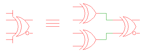
The XOR function is an exclusive-OR when there are two inputs. With more than two inputs, the function is equivalent to a cascade of XOR gates as shown below