6.1.1 Constant Resistance Subcircuit
To download the examples for Module 6, click Module_6_Examples.zip
In this topic:
What You Will Learn
- How to create a constant resistance subcircuit load.
- How to limit the resistance parameter value to positive numbers.
- How to copy a built-in symbol from a global library to a schematic component file.
- How to edit symbols using the Symbol Editor.
Model Requirements
The constant resistance load should:
- Model a constant resistance for all applied voltages.
- Limit the valid resistance parameter values to positive numbers, not including zero.
- Include a basic parameter editing dialog.
- Be self-contained in a schematic component file.
Model Design Procedure
The design procedure for this model is broken into three parts.
Part #1: Define Connectivity and File Name
To begin the model, you will create a new schematic, place and name hierarchical ports and save the schematic as a schematic component.
- From the SIMetrix/SIMPLIS menu bar, select File ▶ New Schematic. Result: a blank, unnamed schematic sheet opens in the Schematic Editor window.
- Place a Hierarchical Module Port on the schematic:
- From the Schematic Editor Menu, select Hierarchy ▶ Place Module Port or use the keyboard shortcut H.
- Press F5 three times to rotate the port so the pin faces downward and the text is on the top of the schematic as shown below:

- Click the left mouse button to place the module port.
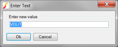
- Double click on the module port to edit the pin name.
Result: The Enter text dialog opens:
- Change the name to P. This will be the positive pin on the symbol.
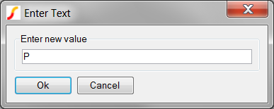
- Click Ok to save the name.
Result: The schematic at this point should appear as:

- Repeat Step 2 to place another module port. This module port will be rotated once and renamed N.
Result: After placing and renaming the two module ports, the schematic will appear approximately as follows: Do not worry too much about the space between the pins, as you can select and move the pins in later steps.

- From the Schematic Editor menu, select File ▶ Save. Result: The Save As dialog opens. The program reads the schematic, finds there are module ports and automatically sets the file type to a schematic component.
- As discussed in the 6.0 Model Requirements topic, you will save your schematic component files to a subdirectory of the main project directory. In this case the subdirectory is Modeling Blocks, and you need to navigate to C:\Training\Module_6_Examples\Modeling Blocks\ to save the schematic component.
- Enter the file name constant_resistance_load as shown below.
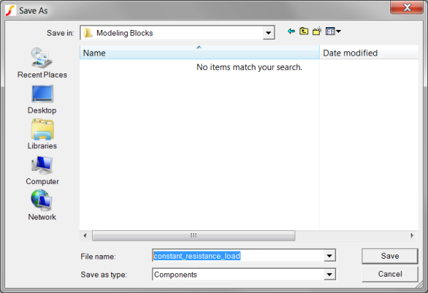
- Click Save to save the schematic component.
At this point you have a basic schematic with two module ports. These module ports will map to the symbol pins, connecting the symbol to the higher level schematic. The constant_resistance_load schematic is currently electrically inactive, in the next part, Part_2:_Add_Resistor_Symbol_and_Parameterize, you will add the electrical definition for the subcircuit.
Part #2: Add Resistor Symbol and Parameterize
In this part, you will add a resistor symbol and parameterize the resistor value.
- Press 4 to add a "Z" type resistor.
- Move the mouse between the two module ports, and click once to place the resistor.
- Wire the resistor to the two module ports. The schematic at this point should
appear similar to:
- Edit the resistor to add a parameter value:
- Double click on the resistor symbol to edit the value. Result: The Choose Component Value dialog opens:
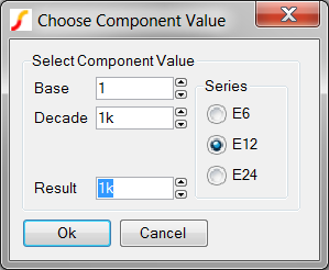
- In the Result field, enter {RESISTANCE}. Result: The completed dialog appears as follows:
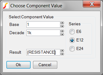
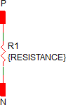
- Click Ok to save your changes. Result: The schematic appears as follows:
- Double click on the resistor symbol to edit the value.
- From the schematic menu, select File ▶ Save to save the schematic.
At this point, the schematic resistor is expecting the parameter RESISTANCE to be passed into the subcircuit from the symbol. The RESISTANCE parameter value can be set with a variable statement at a higher level, or hand-typed into a dialog. While the dialog can limit the parameter value, there is still the possibility that the symbol property itself has the parameter value passed to it inside an expression. When evaluated, this expression could result in a negative resistance value which is out of the desired range. In the next part, Part_3:_Check_Passed_Parameter_Value_With_dot_error, you will learn about the .ERROR statement, which allows you to halt the simulation if a parameter value is less than a minimum value.
Part #3: Check Passed Parameter Value With .ERROR
In this part you will learn how to use the .IF/.ENDIF and .ERROR constructs to check if a parameter value is within a desired range.
- Press F11 to open the Command (F11) Window.
- Copy the following three lines of text and paste into the F11 window.
.IF { RESISTANCE < 1p } .ERROR "The resistance parameter (RESISTANCE) for the constant_resistance_load subcircuit must be >= 1p Ohms." .ENDIF - Make sure the three lines were copied over correctly. Each line should begin with a period. If any lines do not begin with a period, you will need to remove the line breaks to make each line begin with a period. The text in the F11 window automatically word wraps. You may need to stretch the schematic window to verify the lines start with a period.
- From the schematic menu, select File ▶ Save to save the schematic.
There should be three lines in the F11 window. The first line is a conditional test:
.IF { RESISTANCE < 1p }
On the above line, the resistance value is checked to see if the value is less than 1p Ohm. Any value less than 1p Ohm will test true, and the .ERROR statement on the next line is executed:
.ERROR "The resistance parameter (RESISTANCE) for the constant_resistance_load subcircuit must be >= 1p Ohms."
When a .ERROR statement is reached, the netlist preprocessor will stop the simulation from proceeding. In section Test_the_Model, you will purposely set the resistance parameter value less than the minimum limit and verify the error statement is working properly.
If the RESISTANCE parameter is 1p Ohms or greater, the simulation proceeds normally.
Symbol Design Procedure
The symbol design procedure is broken into two parts:
Part #1: Assign and Edit a Symbol
At this point, the subcircuit load has a complete schematic but no symbol. In this section you will learn how to reuse the graphical elements from built-in symbols for your own custom symbols. In this case you will take the graphical portion of the built-in Z-shaped resistor symbol and use this to start your symbol.
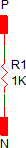
- Select R1, the "Z" shaped resistor symbol.
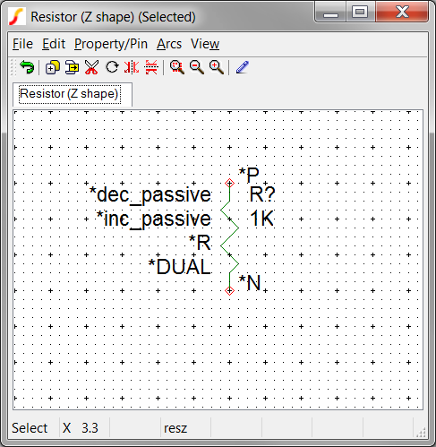
- Right click and select Edit Symbol...
Result: The global symbol for the Z-shaped resistor opens in the symbol editor: Note that you are NOT editing the instantiated resistor symbol for the subcircuit load.
- It is very important to save this symbol to your schematic component file
before
you start to edit it. If you make edits to this symbol and inadvertently save
them, those changes would be applied to the global resistor symbol used by other
schematics. This could have disastrous effects in other schematics. To save the
symbol to your schematic component file,
- Select the Symbol Editor menu File ▶
Save...
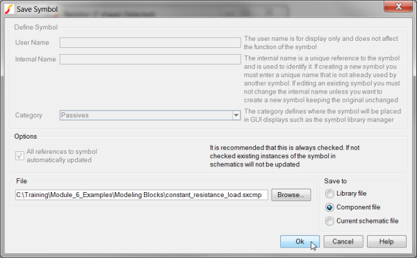
Result: The Save Symbol dialog opens
- In the Save to radio button group, select Component file.
- Click the Browse... button to navigate the file system and select
the schematic component file for the constant_resistance_load. Result: The configured dialog will appear as follows:
- Select the Symbol Editor menu File ▶
Save...
- Delete unneeded symbol properties INCSCRIPT, DECSCRIPT, and
VALUE.
- Position the mouse over the *dec_passive text and left click once.
This text is the property value of the DECSCRIPT property. Result: The text changes color from black to blue, indicating the property is selected.
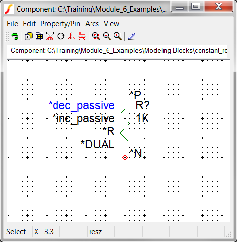
- Press the Delete key to delete the property.
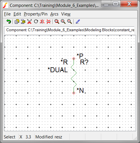
- Repeat for the text *inc_passive and 1K. These two property
values are associated with the INCSCRIPT and VALUE properties.
Result: At this point the symbol editor should appear as follows:
- Position the mouse over the *dec_passive text and left click once.
This text is the property value of the DECSCRIPT property.
- To tell the netlister to instantiate a subcircuit model for this symbol, you need
to edit the MODEL property and change the property value to X by
doing the following:
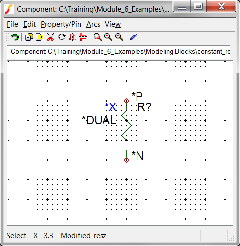
- Position the mouse over the *R text and left click once. Result: The text changes color from black to blue, indicating the property is selected.
- Press F7 to edit the MODEL property. Result: The Edit Property dialog opens:
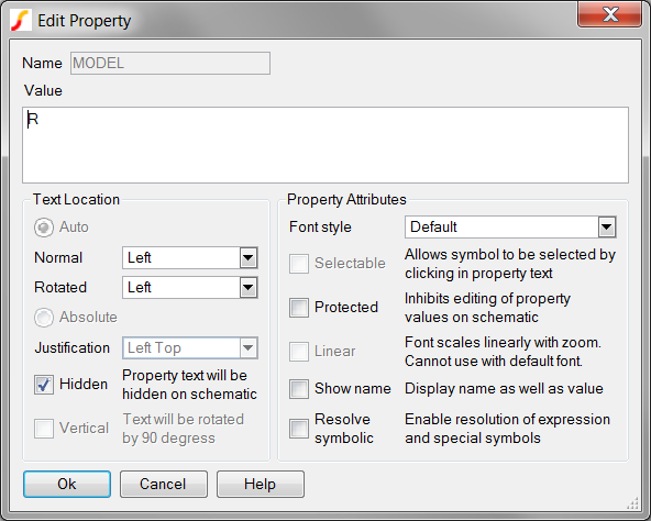
- Change the Value to X, and Click Ok. Result: The symbol editor now appears as follows:
- Position the mouse over the *R text and left click once.
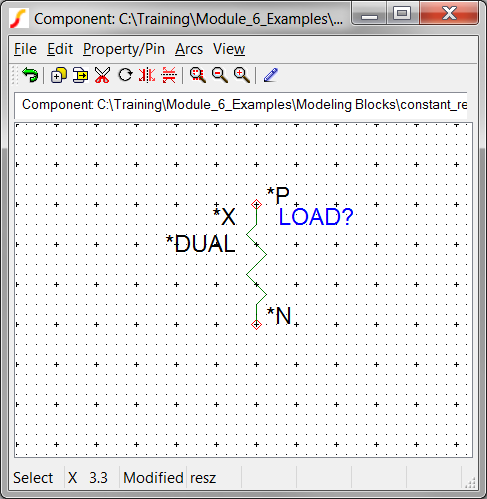
- Change the REF property to LOAD?.
- Select the R? text and repeat Steps 5 A-C, changing the REF
property to LOAD?
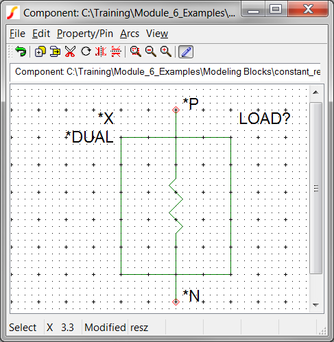
Result: The symbol now appears as follows:
- Select the R? text and repeat Steps 5 A-C, changing the REF
property to LOAD?
- Next, you will modify the graphical representation so users will know this is not
the built-in resistor model.
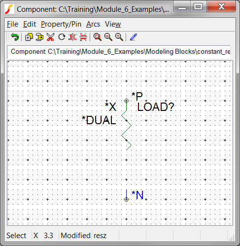
- Position the mouse over the N pin, then press and hold the mouse button
while dragging the pin downwards two major grid ticks. Result: The N pin is now two grid ticks down from the original position.
- Repeat for the P pin, moving the pin up two grid ticks. Result: The P pin is now two grid ticks up from the original location.
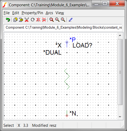
- Position the mouse over the N pin, then press and hold the mouse button
while dragging the pin downwards two major grid ticks.
- Connect the pins to the Z-shaped resistor lines and add a graphical box around
the resistor.
- Double click to start a graphical "wire" segment.
- Left click once to define a corner or end point.
- Right click to stop wiring.
- If you make a mistake, right click to stop wiring and press Ctrl-Z
to undo. Result: The symbol should appear approximately as follows:
- Select the Symbol Editor menu File ▶ Save... to save the symbol to the schematic component file.
You now have a symbol which will call a subcircuit based load model. The functionality of the underlying subcircuit is implied by the Z-shaped resistor, and the box around the resistor suggests to the user that this is not a normal resistor. At this point the symbol doesn't pass the RESISTANCE parameter to the underlying subcircuit, nor does the symbol have a parameter editing dialog. In the next part, Part__2:_Add_RESISTANCE_Parameter_and_Dialog_Properties, you will use a spreadsheet to add the RESISTANCE symbol property, the critical SIMPLIS_TEMPLATE property, and the dialog definition properties.
Part #3B: Add RESISTANCE Parameter and Dialog Properties
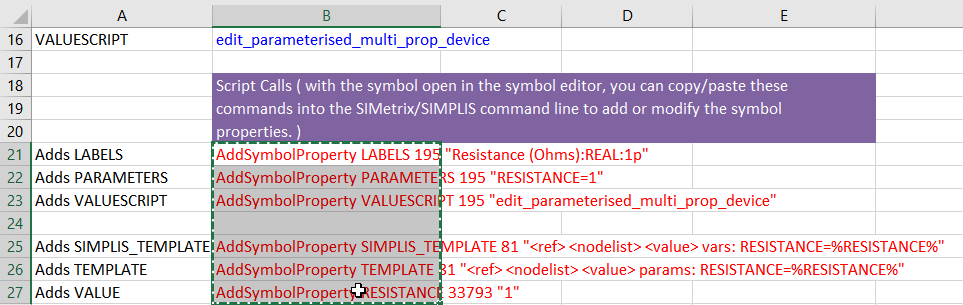
Included in the Module_6_Examples.zip file is a pre-prepared dialog definition spreadsheet similar to the ones used in the previous module. Unlike many previous spreadsheets, this spreadsheet includes commands to add the SIMPLIS_TEMPLATE, TEMPLATE (for SIMetrix simulations) and RESISTANCE symbol properties. The extracted file is located at: C:\Training\Module_6_Examples\6.1.1_constant_resistance_load_dialog_definition_worksheet.xlsx
To add the symbol properties,
- Open the 6.1.1_constant_resistance_load_dialog_definition_worksheet.xlsx excel spreadsheet.
- Copy the six cells: B21-B27 to the windows clipboard.
- Navigate to the SIMetrix/SIMPLIS command shell window.
- Click the mouse in the command line entry located at the top of the command shell
window:
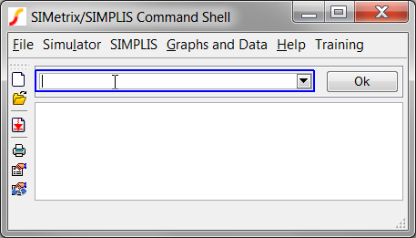
- Press Ctrl+V to paste the commands in the command line.Result: the last command is partially visible in the command line.
- Press Enter or click the Ok Button on the command line.Result: The commands are executed in SIMetrix/SIMPLIS. Each AddSymbolProperty command adds a single symbol property to the symbol. As in previous exercises, the dialog definition properties are protected. All properties are hidden from view when the symbol is placed on the parent schematic.
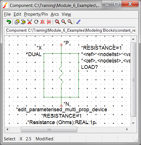
- Select the Symbol Editor menu File ▶ Save... to save the symbol to the schematic component file.
The model and symbol are now complete and ready for testing.
Test the Model
Now that the model and associated symbol are completed, its time to start testing. A testbench schematic for the subcircuit load is located in the Module_6_Examples directory. After you place the subcircuit load, this test schematic is ready to simulate. You will then run a few experiments on the model to verify it works as expected.
To start testing the model, follow these steps:
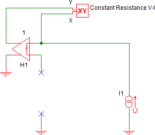
- Open the 6.1_test_constant_resistance.sxsch schematic.Result: The testbench schematic opens, this schematic has been specially prepared to test the load using an XY probe and a ramped current source.:
- From the Schematic Editor menu select Hierarchy ▶ Place Component (Relative Path)....
- Select the constant_resistance_load.sxcmp component file from the Modeling Blocks directory.
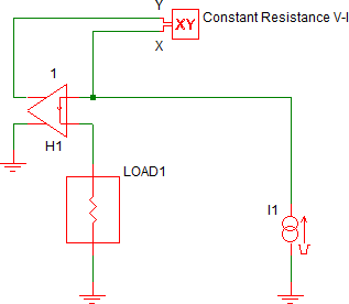
- Place the load on the schematic where the opening below H1 is located.
- Press F9 to run the simulation.
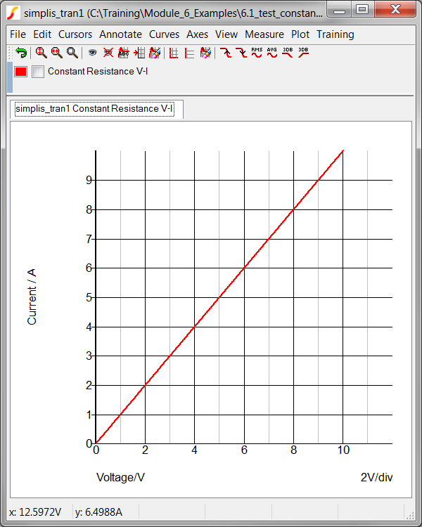
Result: The V-I curve for the load is generated. The resistance used is the default value, which is 1 Ohm:
Experiment #1: Test Dialog and Change Resistance Value
Whenever you pass parameters to subcircuits, it is important to test that the parameters are being passed properly and the simulation results reflect the actual parameter value. In this experiment, you will change the resistance parameter to 2 ohms and verify the value changes in the simulation.
- Navigate to the Schematic Editor window.
- Double click on the subcircuit load symbol to edit the resistance parameter.
Result: The parameter editing dialog opens:

- Change the Resistance value to 2, and click Ok to accept the dialog.
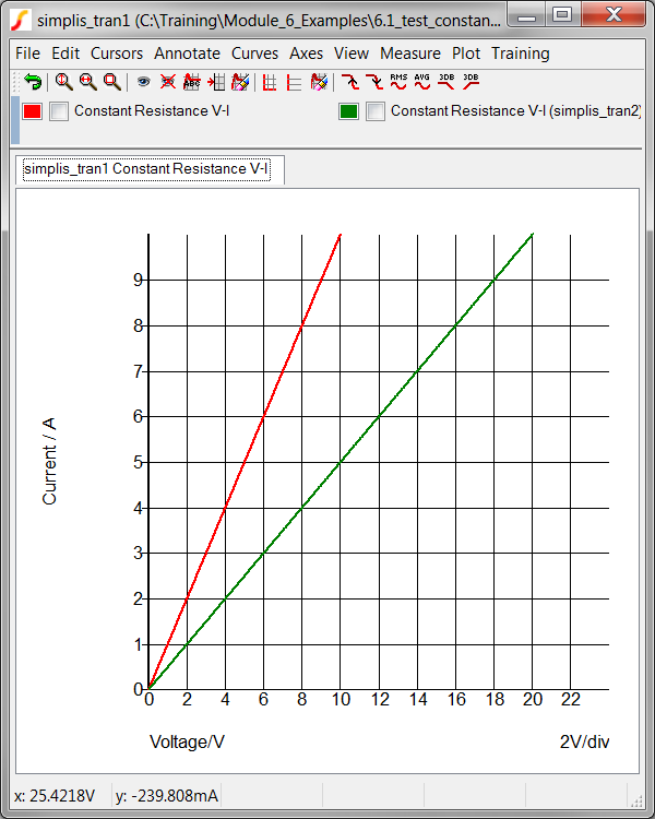
- Press F9 to run the simulation. Result: The V-I curve for the load is generated with the RESISTANCE parameter set to 2 Ohms (green curve). As expected, the slope of the V-I curve, which is the resistance, is 1/2 the value in the earlier experiment.
Experiment #2: Test .ERROR Message
Testing the .ERROR message is slightly more difficult because the parameter editing dialog will not allow you to enter an invalid value. Instead you will manually edit the value using the Edit Properties dialog.
- Select the LOAD1 symbol.
- Right click and select the Edit/Add Properties... menu option. Result: The Edit Properties dialog opens:
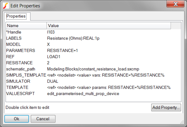
- Double Click on the RESISTANCE entry. Result: The Edit Property dialog opens.
- Change the Value to 0, and click Ok on the Edit Property dialog to accept the changes.
- Click Ok on the Edit Properties dialog.
- Press F9 to run the simulation.Result: The RESISTANCE parameter is less than the minimum limit specified in the F11 window of the constant_resistance_load.sxcmp schematic, and the .ERROR statement text is output to the command shell: The program adds the first line, indicating which subcircuit definition and instantiation the .ERROR statement originates from.
*** ERROR *** (6.1_test_constant_resistance.net): Subckt def constant_resistance_load used by X$LOAD1:
The resistance parameter (RESISTANCE) for the constant_resistance_load subcircuit must be >= 1p Ohms.
Experiment #3: Test Minimum Resistance Value Allowed by Dialog
In the previous experiment you set the resistance to a value less than the minimum allowed by the parameter editing dialog. In this short experiment you will verify the dialog prevents users from entering values less than the specified minimum value.
- Double click on the LOAD1 symbol to open the parameter editing dialog.
Result: Although the RESISTANCE symbol property value was set to 0 in the last experiment, the dialog automatically changes the value to 1p, which is the minimum allowed value.
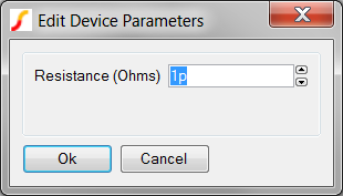
- Press the up arrow button on the spinner control. Result: The Resistance value changes from 1p to 2p.
- Press the down arrow button twice on the spinner control. Result: The Resistance value changes from 2p to 1p, and on the second click, the minimum value of 1p is enforced.
Conclusions and Key Points to Remember
The constant resistance load used in this example is a very simple subcircuit definition. In this topic, you have added a "subcircuit wrapper" around a primitive resistor model. While at first this seems like unnecessary overhead, the resulting model now has a custom dialog with built-in error checking which makes the model more robust, modular and easier to use. As you build higher level models, exploiting the subcircuit interface will allow you to easily manage and reuse your models. When you put together the individual subcircuit loads into a single symbol/model in section 6.2 Assembling the Subcircuit Load, the importance of model reuse and the subcircuit wrapper will become clear.
Key points to remember are:
- You can limit the range of valid parameter values with the .ERROR statement.
- You can copy a built-in symbol from a global library to a schematic component file, then edit it to suit your needs, saving time.