v9.30 Header

Schematic Editor Features
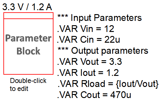
Parameter Block

Parameters and expressions can now be placed and viewed on the schematic using a Parameter Block.  Multiple configurations can also be held in a single Parameter Block, allowing the user to easily switch between sets of parameters.

When parameters are placed in a Parameter Block, they are accessible by the top-level schematic as if they were defined in the F11 window.

parameter block
Simulator: SIMetrix and SIMPLIS
Required Version: All versions
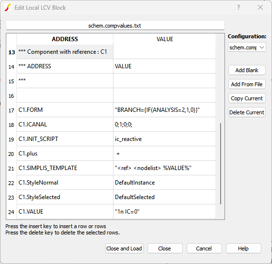
Local LCV Block

The Local LCV Block is a symbol that can be placed on a schematic and can hold multiple LCV configurations.  Each configuration can be viewed, edited, saved, and/or loaded via the symbol's dialog.

local LCV dialog
Simulator: SIMetrix and SIMPLIS
Required Version: All versions

New Features for the SIMPLIS Simulator
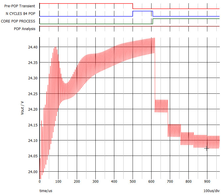
Pre-POP Transient Analysis

An optional Pre-POP Transient analysis is added as a subtask of the Periodic Operating Point (POP) analysis. The Pre-POP Transient analysis, if enabled, is the first subtask to be run in the POP analysis. The Pre-POP Transient analysis stops when either it has reached the specified stop time or when the logic output of a certain triggering gate has registered a 0-to-1 transition. After the Pre-POP Transient analysis has finished, the simulation of the “N cycles before launching POP” is run next, followed by the core POP process. The Pre-POP Transient analysis is useful for complex systems requiring extensive initialization of a large number of energy-storage elements and sequential logic circuits, allowing the core POP process to be launched only after the system has settled to a reasonable starting point.

In addition, if the Pre-POP Transient analysis is enabled, the POP analysis now supports automatic resetting of the “Maximum period” parameter according to the switching periods observed by the POP trigger during the Pre-POP Transient analysis.

ppt example waveforms
Simulator: SIMPLIS
Required Version: All versions
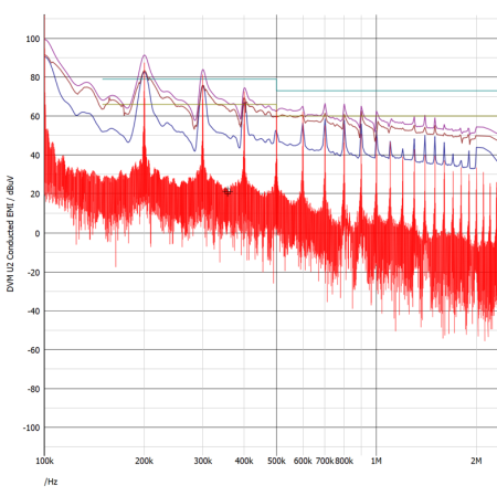
LISN Updates

The SIMPLIS LISN device can now take noise measurements similar to those of an EMI detector defined by the CISPR16.1 standard. In addition to the FFT of the total conducted EMI voltage waveform that was available previously, the user can now select to also show peak, quasi-peak, and/or average EMI measurements. These curves, calculated after the simulation is finished and giving results analogous to passing the LISN's total conducted EMI voltage waveform through an EMI detector, are overlaid on the same graph as the FFT and can therefore be easily compared to noise limits defined in various EMI standards.

LISN waveforms
Simulator: SIMPLIS
Required Version: All versions

New Features for the SIMetrix Simulator
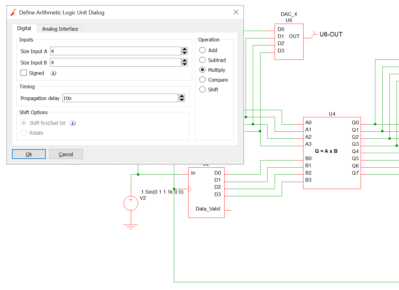
Digital Simulator Generic Models

A range of new generic models is now available. These include:

  • Logic gates with optional inverted inputs and complementary outputs. All types available: AND, OR, NAND, NOR, XOR, and XNOR
  • Flip flops and latches. Includes D-type, JK, SR, Toggle, and D-type latch. All offer detailed timing specifications
  • An Arithmetic/logic unit provides 5 operations: add, subtract, multiply, compare, and parallel shift
  • Multiplexer
  • Demultiplexer
  • Up/down counter with parallel load
digital devices


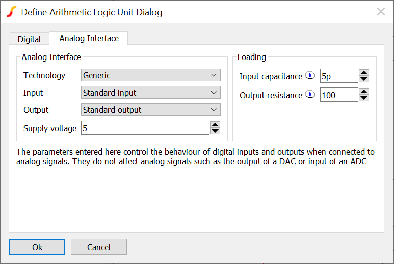
Digital Simulator Enhanced Analog Interface

The analog interface to the digital simulator has been improved. For the generic devices, the technology used to implement the part can be changed on a per-device basis. Technologies available include standard HC 5V, LV 3.3V, LV 5V, LVC 1.8V, LVC 2.5V, LVC 3.3V and 4000 series 15V. Further, the operating voltage may be overridden to any desired value.

In addition to the analog improvements, the digital plotted waveforms now reflect the operating voltage.

analog interface


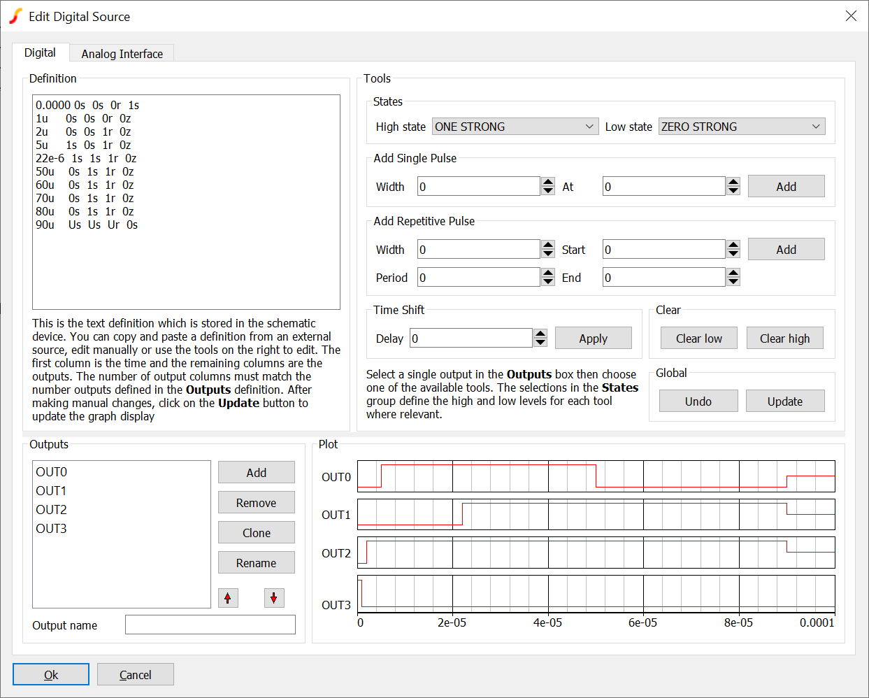
Digital Simulator Sources

A new user interface has been developed for the digital source. While the underlying simulator device was available in previous versions, it required a manually generated text file to configure it. Now there are two new user interfaces: one provides multiple arbitrary output waveforms, and the other a fixed constant value.

digital sources
Simulator: SIMetrix
Required Version: All versions
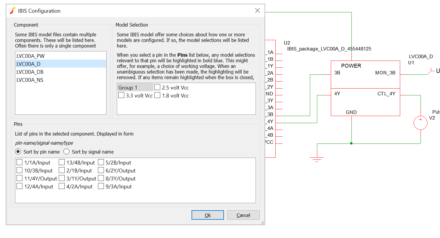
IBIS Models

IBIS (Input/Output Buffer Information Specification) is a specification for digital input and output stages. IBIS models are widely available from most digital device manufacturers and allow the simulation of analog interfaces and interconnect systems.

ibis dialog
Simulator: SIMetrix
Required Version: Pro or Elite

How to get version 9.30

For those interested in evaluating SIMetrix/SIMPLIS 9.30, please head to the Evaluation page and follow the directions to obtain a trial license.

For those who are up to date on their maintenance, the installer can be downloaded by clicking the button above. If you do not possess the credentials for downloading the new version, please contact us at sales@simplistechnologies.com.