Advanced Inductor Modeling
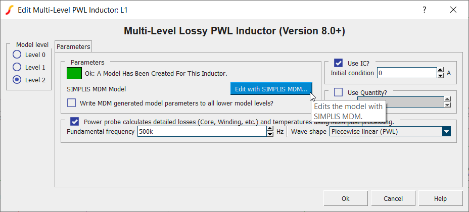
For inductors, SIMPLIS MDM is accessible using the new Level 2 model of the Multi-Level Lossy PWL Inductor:
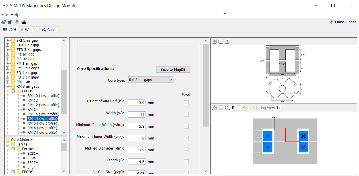
MDM provides a new window with an intuitive GUI to build an inductor by selecting a core material, core shape and size, wire material, wire shape and size, bobbin, and number of turns. The user can select standard sizes from the catalogue or define custom sizes.
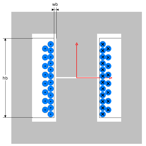
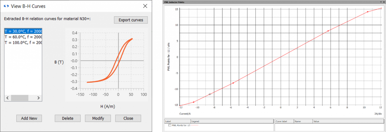
Using the B-H curves of the selected material stored in MDM’s database, a reluctance model of the defined core and an accurate 3D model of the airgaps, a piecewise-linear inductance for the inductor is calculated and used in the SIMPLIS circuit simulation:
Advanced Transformer Modeling
For transformers, MDM is accessible using the Level 3 model of the new Multi-Level Lossy Transformer symbol:

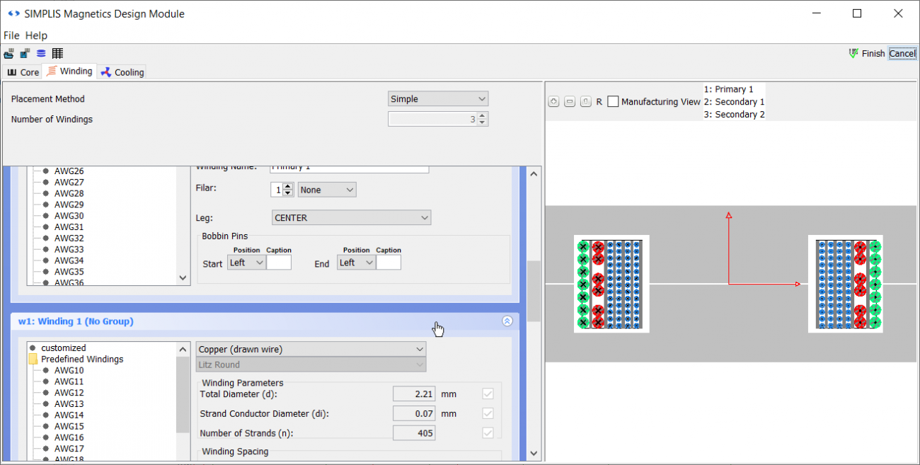
The MDM GUI for transformers allows for the design of each transformer winding in detail:
For transformers, a reluctance (magnetic circuit) model is simulated directly inside the SIMPLIS schematic to obtain accurate currents and voltages for each winding and accurate fluxes in each part of the transformer core.
Detailed and Accurate Loss Analysis
A large part of inductor and transformer losses are non-linear and cannot be accurately represented simply by a constant resistance in the circuit schematic. Therefore, SIMPLIS MDM provides a post-processing option to accurately calculate DC and AC winding losses (including skin and proximity effect, and the proximity losses due to the core air gaps) as well as core losses accounting for the effect of different waveform shapes, DC current, and temperature. Once the circuit simulation is complete, MDM uses the resulting waveforms to calculate the inductor or transformer loss and temperature.
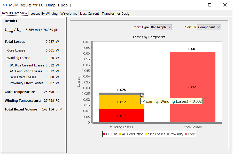
A loss breakdown is given so that the critical losses can be identified:
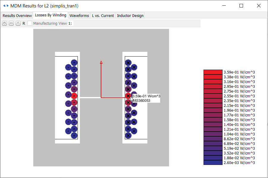
A loss by turn diagram can show whether the winding losses are primarily due to the air gap, winding arrangement, or DC resistance:
Thermal modeling
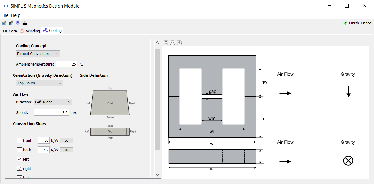
The detailed loss calculations can be performed assuming a constant temperature. Alternatively, the user can define a detailed cooling arrangement for the inductor or transformer, including sides exposed to heat flow, the presence of heat sinks, the ambient temperature, the usage of natural or forced convection, the speed of airflow, and the orientation of the component:
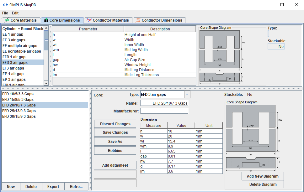
MagDB – MDM’s magnetic parts database
MDM’s database can be edited and extended by the user to add new material and standard core and wire definitions. It will also be updated periodically with new data with program updates.
To learn more about SIMPLIS MDM, click here.
Example Circuits That Require a Full SIMetrix/SIMPLIS License and the Magnetics Design Module
| SIMPLIS MDM Buck Converter | An inductor for the fixed frequency synchronous buck converter from the SIMPLIS Tutorial, designed, simulated, and post-processed using MDM. |
| SIMPLIS MDM PFC Boost Inductor | A boost inductor designed in MDM for the constant on-time PFC converter. A standard SIMPLIS example. |
| SIMPLIS MDM Self-Oscillating Flyback Transformer | A flyback transformer designed, simulated, and post-processed using MDM for the self-oscillating converter that regulates a 5-V/2-A output from a 300 - 350-V input (another standard SIMPLIS example). |
| SIMPLIS MDM LLC Resonant Inductor Transformer | The standard SIMPLIS LLC half-bridge converter example modified so that it is on open-loop, with both the resonant inductor and the power transformer designed using MDM. |